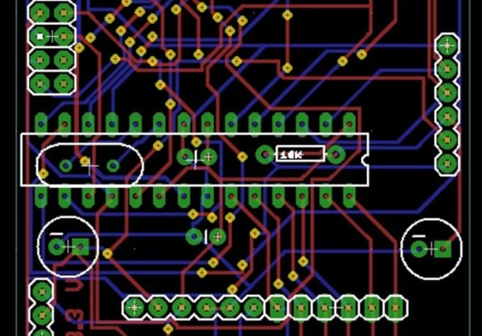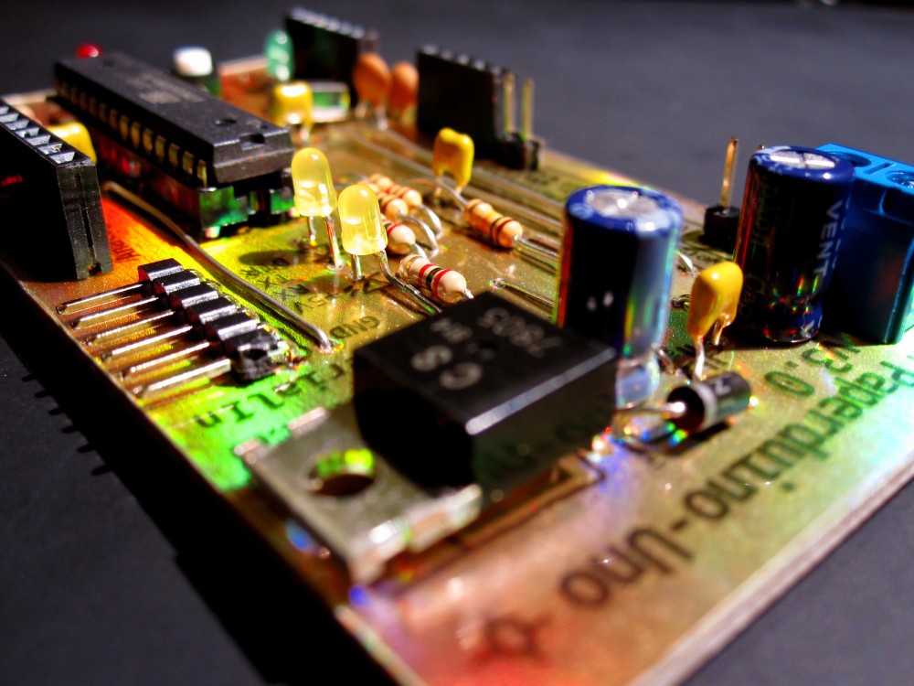

But I have not found any explanation for the rest of the code. The cryptic names have a kind of encoding that is somewhat consistent R = resistor, C = capacitor, etc. I agree that the 3D renderings are essential to working out the PCB design. Please feel free to offer any advice that you think may help me along in this endeavor. From there I found an Arduino component library that I have also downloaded for use with the program. There is also a DipTrace forum available that may be helpful with specific questions.

To this end, I am just getting my feet wet and will require lots of help.Īt this point, I have downloaded and installed the freeware version of DipTrace and am reviewing the tutorial and help system topics. These include ABS signaling, block control, and automated train operations. My plan is to make use of DipTrace to integrate an Arduino Nano with various other components for certain model railroad projects that I have in mind. I am just getting started with DipTrace and am in need of some guidance from the members of this forum who have more experience with this tool Gunrunnerjohn, Tom (aka rtr12), and Mjcat have already offered some good advice.

This is a continuation of a discussion that developed from an older thread called "Semaphore and 555 Timer Circuit" that seems to have meandered away from its original topic. I've decided to open this new thread about PCB (printed circuit board) design using the DipTrace program.


 0 kommentar(er)
